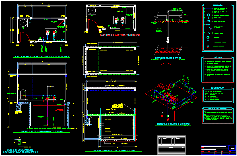
Water Line Cad Drawings

PART 1 COMMON FOR WATER & WASTEWATER CONSTRUCTION TITLE Pg. By Other Than Open Cut (Non-T.x.D.O.T. Non Railroad) - 101 Highway Crossing - All Wastewater Mains & Wate r Mains 12' and Smaller in Diameter.
Listed below are links to the PDF construction standard details. Many of these files are large (over 2 MB). Please be patient while they download.
INDIVIDUAL DETAIL DRAWINGSBattle chess game of kings.
CAD drawings need to be opened up in Chrome or Firefox.
WATER
Temporary Blow-Off Assembly – [PDF] [CAD]
Permanent Blow-Off Assembly – [PDF] [CAD]
Air-Release Manhole – [PDF] [CAD]
Fire Hydrant Assembly – [PDF] [CAD]
Tapping Sleeve and Valve Assembly – [PDF] [CAD]
Standard Bore Encasement – [PDF] [CAD]
Vertical Bend Rodding and Blocking Detail – [PDF] [CAD]
Thrust Block Detail – [PDF] [CAD]
Thrust Collar Installation – [PDF] [CAD]
Restraint Harness – [PDF] [CAD]
Large Culvert Crossing Detail – [PDF] [CAD]
Storm Sewer Crossing Detail – [PDF] [CAD]
Valve and Valve Box Installation – [PDF] [CAD]
Concrete Protector Ring – [PDF] [CAD]
Valve Marker – [PDF] [CAD]
HDPE Pipe Connection – [PDF] [CAD]
Pipe Laying Condition – [PDF] [CAD]
Cutting and Replacing Pavement – [PDF]
¾” and 1” Yard Hydrant – [PDF] [CAD]
Standard Water Tap – [PDF] [CAD]
¾” and 1” Water Meter Service – [PDF] [CAD]
1 ½” Water Service w/ RPZ and BFP – [PDF] [CAD]
2' Water Service with RPZ and BFP - [PDF] [CAD]
3” Water Service with BFP-Above Grade – [PDF] [CAD]
3” and Larger Water Service w/BFP-Below Grade – [PDF] [CAD]
Manual Air Relief Valve Assembly – [PDF] [CAD]
Standard Gang Meter Assembly – [PDF] [CAD]
SEWER/FORCE MAIN
Standard Manhole Frame and Cover – [PDF] [CAD]
Standard Outfall Manhole Frame and Cover – [PDF] [CAD]
Lockable Manhole Frame and Cover – [PDF] [CAD]
Standard Precast Concrete Manhole – [PDF] [CAD]
Inside Drop Manhole – [PDF] [CAD]
Typical Shallow Manhole – [PDF] [CAD]
Typical Vented Manhole – [PDF] [CAD]
Typical Manhole Invert – [PDF] [CAD]
Polypropylene Plastic Manhole Step – [PDF] [CAD]
Pipe Laying Conditions A & B – [PDF] [CAD]
Pipe Laying Conditions C & D – [PDF] [CAD]
Pipe Laying Conditions E – [PDF] [CAD]
Aerial Pipe Supports – [PDF] [CAD]
Aerial Pipe Support Detail: 39A [PDF] [CAD] 39B [PDF] [CAD]
Typical Storm Sewer Crossing – [PDF] [CAD]
Typical Sewer Service Connection – [PDF] [CAD]
Air Vacuum/Pressure Release Valve in Manhole – [PDF] [CAD]
PUMPING
Basket Strainer Manhole – Section View – [PDF] [CAD]
Basket Strainer Manhole – Plan View – [PDF] [CAD]
Submersible Pump Station Plan & Section – [PDF] [CAD]
Submersible Pump Station Rainhood – [PDF] [CAD]
Submersible Pump Station Electrical Riser Detail – [PDF] [CAD]
Chain Link Fence - [PDF] [CAD]
Gate Detail (48B) - [PDF] [CAD]
CONNECTION TO PRESSURE SEWER SYSTEMS
Septic Tank Effluent Pump – [PDF] [CAD]
Standard Detail Pressure Sewer – [PDF] [CAD]
Junction Box and Motor Control Panel – [PDF] [CAD]
Wooden Antenna Pole Installation Detail – [PDF] [CAD]
RECLAIMED WATER
Standard Reclaimed Water Tap Detail – [PDF] [CAD]
¾ and 1” Reclaimed Water Service Detail – [PDF] [CAD]
1½” and 2” Reclaimed Water Service Detail – [PDF] [CAD]
Tapping Sleeve and Valve Assembly – [PDF] [CAD]
Hydrant Assembly – [PDF] [CAD]

With version 2 of PLUMBER, our software for water supply systems design in buildings, it is now possible to create Plan and Isometrics views of the water network you are designing. You will see below this new feature’s details.The Plan and Isometrics views creation in PLUMBER 2.0 is conditioned upon, at least, that the nodes that make up the water supply system have values other than 0 for its X and Y coordinates.